VLANs with Linux, NFTables and Ubiquiti Unifi

While setting up my new Ubiquiti Unifi WiFi access points, I spent more time than I’d like to admit troubleshooting my new guest network before I got it to work, so that topic is the basis for this post. The problem I encountered turned out to be completely trivial and I’ll spend a paragraph further down detailing it, but I’ll describe the necessary VLAN and firewall configurations in some detail as it’s sure to help somebody down the line.
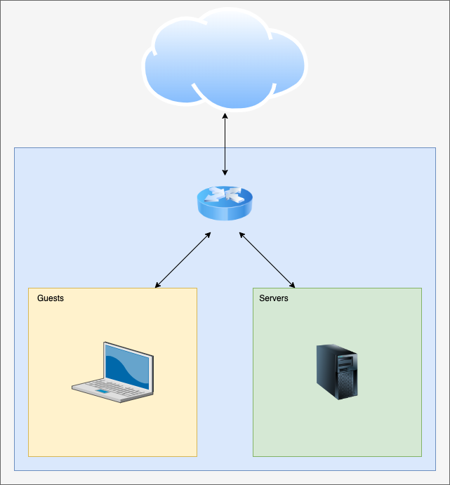
The point of a guest network, of course, is to give people with untrusted devices a way of accessing the Internet using your infrastructure while preventing them from accessing your own devices and/or servers. In this way you lessen the risk – for example – of potential malware on your friend’s computer causing issues on your own gear.
The components involved: – Network equipment that can understand at least Layer 2 VLAN (IEEE 802.1q). – A router/firewall to allow select network traffic to pass as required while blocking unnecessary traffic.
For the network equipment, my current setup consists of my trusty Linux-based router, a couple of L2 VLAN capable managed SOHO switches, and two Ubiquiti Unifi access points.
Switches
The first thing I did was to decide on a VLAN ID to use, and to configure my switches to “tag” traffic for this VLAN for all ports while my default VLAN stayed “untagged”. As mentioned, I have SOHO switches meaning the configuration possibilities are limited, but this is how it looks in a current D-Link switch:

Without going too much into detail, an untagged VLAN on a switch port means that this is the default network for the port. Anything connected to the port with no additional configuration will see that VLAN. Tagging a VLAN in a port means that the VLAN is available to devices connected to the port that ask to see traffic associated with that VLAN ID.
Note that Ubiquiti Unifi access points are VLAN capable for WiFi networks, but they can only be managed through the untagged VLAN whichever it is.
Router VLAN setup
As I’ve mentioned, my router runs Ubuntu Server. Its onboard Intel network interfaces are VLAN capable, but we need to tell the Linux kernel to enable the capability:
sudo apt install vlanWe can load the kernel module:
sudo modprobe --first-time 8021q..And we can verify it:
sudo modinfo 8021q
filename:       /lib/modules/5.4.0-122-generic/kernel/net/8021q/8021q.ko
version:        1.8
license:        GPL
alias:          rtnl-link-vlan
srcversion:     634123A919317BAF16A45A8
depends:        mrp,garp
retpoline:      Y
intree:         Y
name:           8021q
vermagic:       5.4.0-122-generic SMP mod_unload modversions
sig_id:         PKCS#7
signer:         Build time autogenerated kernel key
sig_key:        71:A4:C5:68:1B:4C:C6:E2:6D:11:37:59:EF:96:3F:B0:D9:4B:DD:F7
sig_hashalgo:   sha512
signature:      11:8B:EE:D0:DE:7D:EF:A5:21:82:35:F1:EB:3A:53:66:B8:B1:4A:F9:
		E4:27:5C:81:04...
With that in place, we’ll set up NetPlan to use VLAN 999 and give us an IP address in that network by editing /etc/netplan/00-installer-config.yaml and adding a vlans section with the same indentation level as the ethernets section above it. We’re using our internal-facing interface for this, which in my case is enp2s0.
/etc/netplan/00-installer-config.yaml
  vlans:
    enp2s0.999:
      id: 999
      link: enp2s0
      addresses: [10.199.254.1/24]
With this, we’ve created a virtual network interface named enp2s0.999 which tags its traffic with ID 999, uses the physical link enp2s0 for connectivity, and we’ve assigned an IP address at the start of subnet range. The config can be tested by running sudo netplan try followed by sudo netplan apply if we didn’t do anything stupid. At this point, we should be able to ping 10.199.254.1 and get responses from our local machine.
DHCP
We need to add some configuration to our ISC-DHCP-Server so that it can hand out addresses in our guest subnet range to clients.
First of all, it has to listen to such requests at all. We start out by editing /etc/default/isc-dhcp-server and modifying the INTERFACESv4 line to add our new virtual network interface. My line looks like this:
/etc/default/isc-dhcp-server
INTERFACESv4="enp2s0 enp2s0.999"As per the instructions in the file, the interfaces are separated by a simple space.
Second, we define the address space and its configuration in /etc/dhcp/dhcpd.conf. I’m not interested in dynamic DNS for this network zone, so my configuration is very simple. In my setup I’ve just added a new subnet clause right below my existing one:
/etc/dhcp/dhcpd.conf
subnet 10.199.254.0 netmask 255.255.255.0 {
    range 10.199.254.100 10.199.254.254;
    option subnet-mask 255.255.255.0;
    option routers 10.199.254.1;
    option domain-name-servers 10.199.254.1;
}
Since I present some services from my server network that I want to be available to my guest network, I’ve elected to use my internal DNS for guests too, but the domain-name-servers option could of course point at an externally hosted service like CloudFlare’s 1.1.1.1 if you don’t have this requirement, which simplifies things slightly.
Setting up a listener and defining a DHCP address range really is all that’s required for this service, so let’s sudo systemctl restart isc-dhcp-server to reload our configuration and continue with the next task.
DNS
As I mentioned earlier this step may be irrelevant in many cases, but I want to present guests with my own DNS service, so I need to make Bind9 too listen to DNS queries from the guest subnet. All the relevant options are in /etc/bind/named.conf.options.
I have my allow-query option set to allow the acl localclients. Near the top of the file right under the acl definition for localclients I add another acl for guests:
/etc/bind/named.conf.options
acl guests {
        10.199.254.0/24;
};
Then in the options block, I add the guests acl to the allow-query option:
/etc/bind/named.conf.options
options {
        (....)
        allow-query { localclients; guests; };
        (....)
};
Finally in the options block I also have a listen-on clause which needs to be modified to listen on our interface in VLAN 999:
/etc/bind/named.conf.options
options {
        (...)
        listen-on { 127.0.0.1; 127.0.0.53; 10.199.200.1; 10.199.254.1; };
};
That’s all, really. Write the changes and sudo systemctl restart bind9 to make them take effect.
NFTables
Finally to make the router configuration come together we need to set up rules so that guests can access only relevant services in our server network, and so they can connect to the Internet. This of course is done in /etc/nftables.conf where we start by defining the variables GUESTLINK, SERVERNETS and INTERNALWEBSERVERS near the top of the file:
/etc/nftables.conf
#!/usr/sbin/nft -f

flush ruleset

define LANLINK = enp2s0
define GUESTLINK = enp2s0.999
define WANLINK = enp1s0

define NET_PRIVATE = {10.0.0.0/8, 172.16.0.0/12, 192.168.0.0/16}
define SERVERNETS = { 10.199.200.0/24 }
define INTERNALWEBSERVERS = { 10.199.200.10/32 }
(...)
Further down, in my input filter, I define a a chain inbound_guest and ensure it’s used for traffic from the guest network specifically to the router, so that we can allow DHCP and DNS traffic:
/etc/nftables.conf
(...)
table inet filter {
        (...)
        chain inbound_guest {
                ip protocol . th dport vmap { udp . 53 : accept, tcp . 53 : accept, udp . 67 : accept }
        }
        chain inbound {
                (...)
                iifname vmap { lo: accept, $WANLINK : jump inbound_world, $LANLINK : jump inbound_private, $GUESTLINK : jump inbound_guest }
        }
(...)
And finally in my forward chain I make sure that guests can reach my internal web server(s) and the Internet but nothing else:
/etc/nftables.conf
        chain forward {
                (...)
                iifname { $GUESTLINK } tcp dport { 80, 443 } ip daddr $INTERNALWEBSERVERS accept
                iifname { $GUESTLINK } oifname { $WANLINK } accept
                (...)
        }
Verify the new config by running sudo nft -c -f /etc/nftables.conf. If it checks out OK, run sudo /etc/nftables.conf to enable the config.
At this point what remains is the Ubiquiti Unifi part.
Unifi network configuration
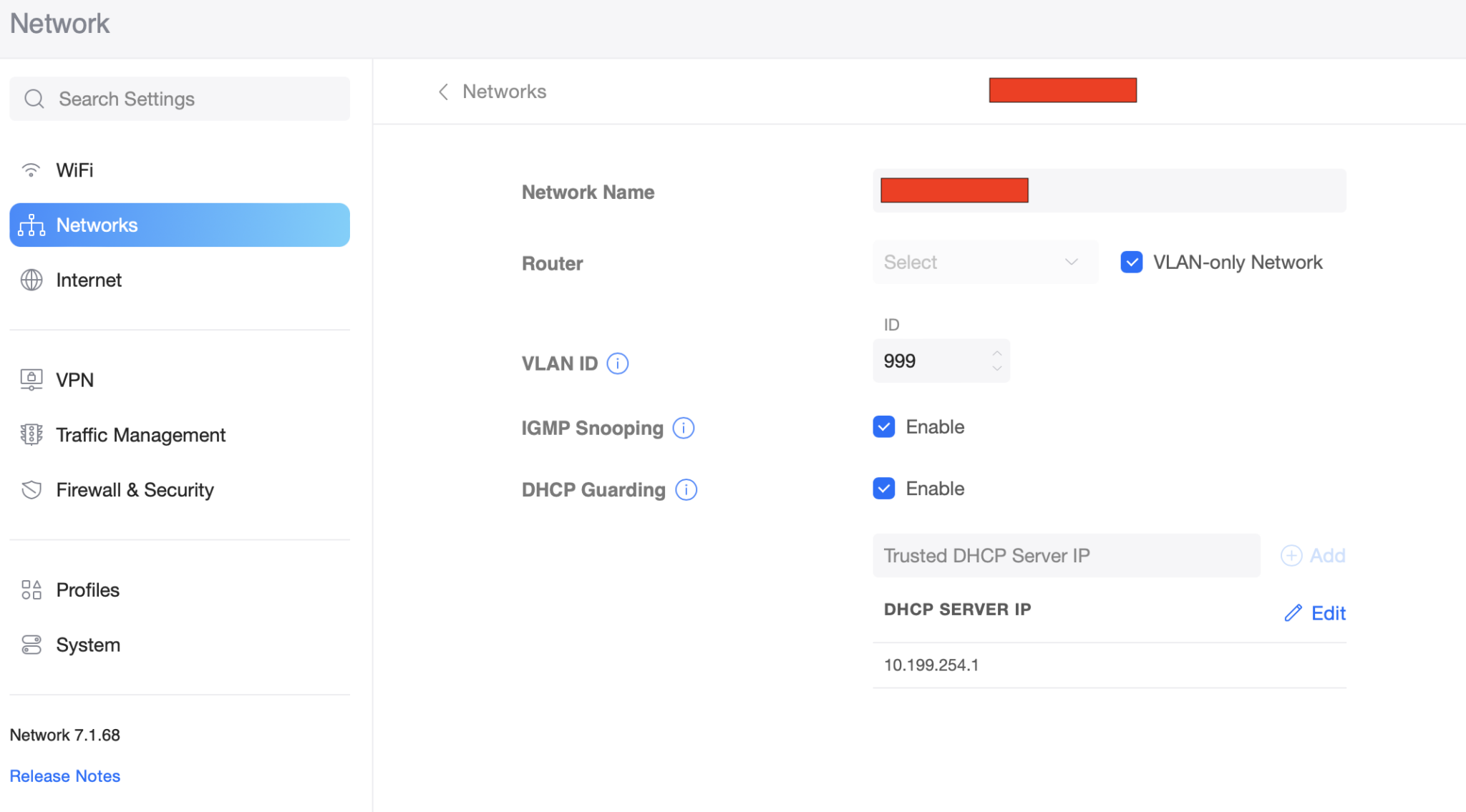
In the Unifi web app, under Settings, open up Networks and click Create New Network. Give the network a name, check the box to define it as a VLAN-only Network, and type in the VLAN ID. This tells Unifi that we’re managing it out-of-band and how to reach it.
I also enabled IGMP Snooping to reduce broadcast chatter, and DHCP Guarding to make it harder for a rogue device to hijack IP address distribution.

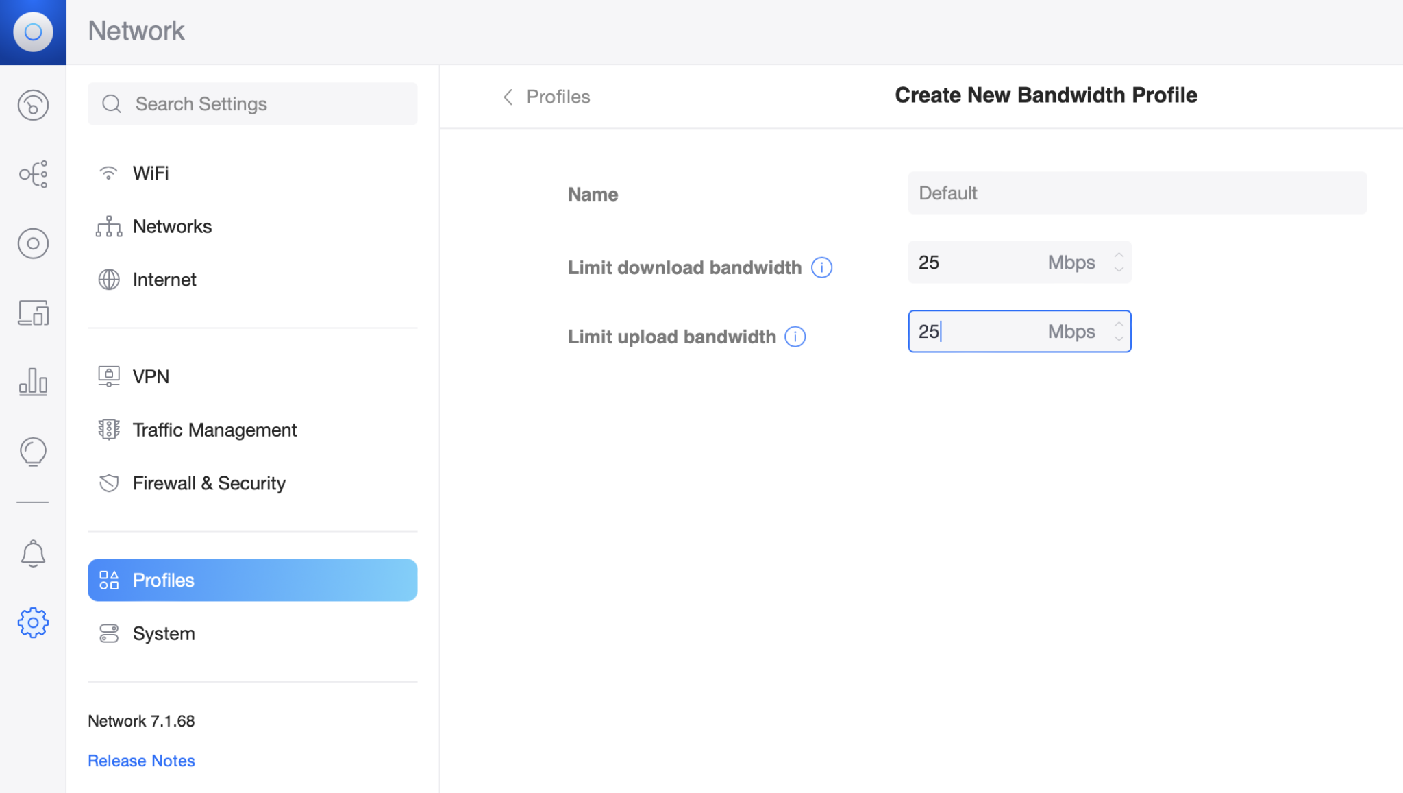
Save the new network and click Profiles to add some guest bandwidth throttling (optional):

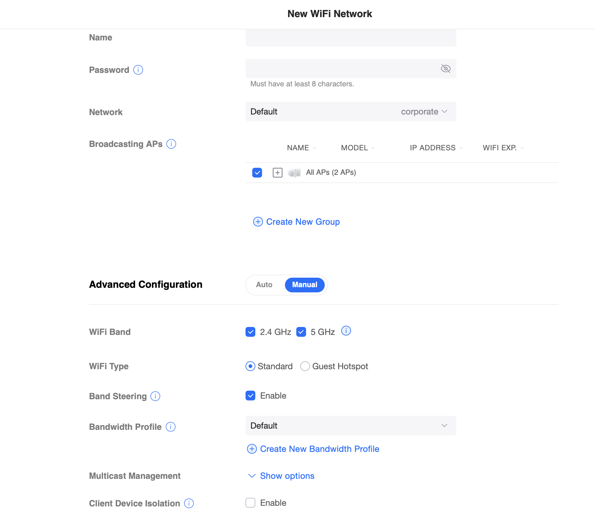
Finally save the profile and click the WiFi settings to set up the guest WiFi network.

What threw me off guard as mentioned at the start of this post, was the WiFi Type option. I thought selecting Guest Hotspot was a good idea, but it turns out we’re really managing these things mostly in our router. In other words: Select Standard for your WiFi Type to avoid issues. Select the Network and Bandwidth Profile you created earlier, check Client Device Isolation, and set up the rest of your options to your taste.
Connecting a computer to the new guest wifi network you can verify that you only reach what you should be able to, that any bandwidth limitations are in place, and that really should be it.